CO.,LTD.")
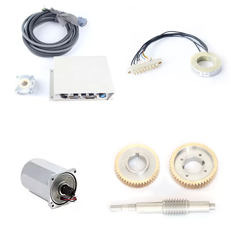


Product Details
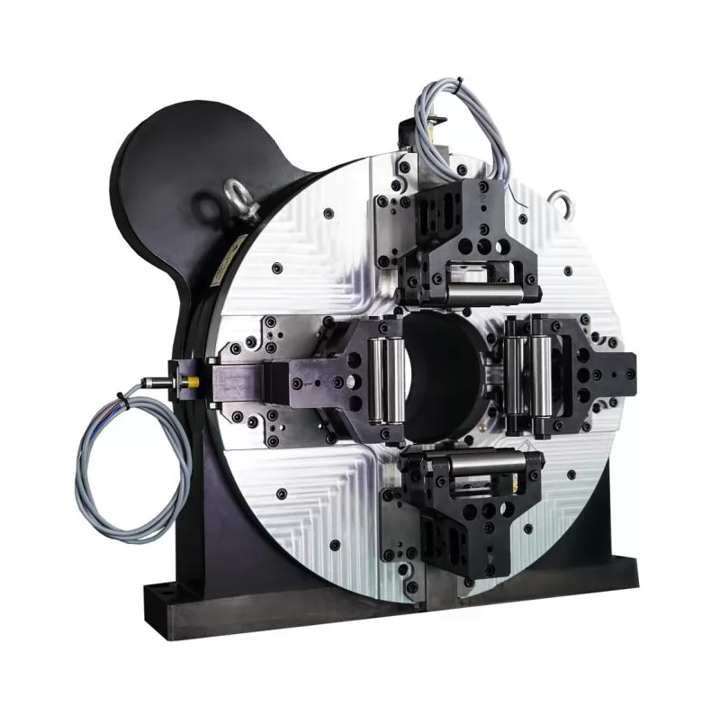
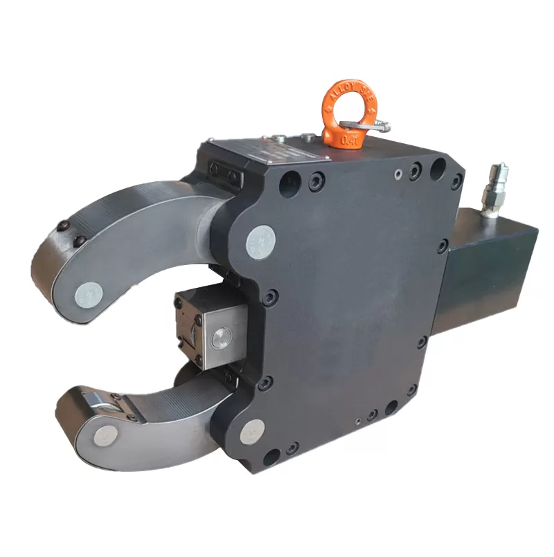
The HY100A center rest includes a clamping device for holding the shaft-like workpiece support to be machined.
It can reciprocate along the machine tool's guide rails relative to the machine's spindle housing through a mounting hole.
The device is mounted on the support shaft, fitting within the mounting hole and coaxially with the machine's spindle.
One end of the support shaft is connected to the clamping device, allowing it to rotate about its own axis.
It is positioned independently of the finished outer diameter, preventing damage to the workpiece surface.
It exhibits excellent rigidity when machining high-pitch threads on the right side, minimizing roundness errors in the machined area.

In mechanical manufacturing, machining of slender shaft parts often involves machining the external diameter,
internal bore, end profiles, and threads. Traditional external turning typically uses a clamping and supporting system.
To increase workpiece rigidity, a steady rest is typically used to support the center of the workpiece.
When machining end profiles, internal bores, and internal threads, a clamping system with one end clamped and the other supported by a steady rest is typically used.
As a manufacturer, we also offer machine tool steady rest modification services, guaranteeing your satisfaction.
Product Size

Product Parameters
| HY-A series center stand specifications, dimensions and technical performance parameters | ||||||||||
| Model | HY65A | HY100A | HY150A | HY200A | HY260A | HY280A | HY310A | HY350A | HY420A | HY520A |
| Clamping diameter range | φ5-φ65 | φ10-φ100 | φ20-φ155 | φ30-φ200 | φ35-φ260 | φ40-φ280 | φ50-φ310 | φ70-φ350 | φ115-φ420 | φ150-φ520 |
| L1(mm) | 231 | 314 | 441 | 520 | 665 | 670 | 743 | 798 | 908 | 948 |
| L2(mm) | 54 | 68 | 104 | 125 | 157 | 161 | 177 | 229 | 258 | 278 |
| L3(mm) | 53 | 100 | 150 | 170 | 230 | 230 | 270 | 240 | 265 | 315 |
| L4(mm) | 94 | 110 | 148 | 175 | 208 | 208 | 228 | 235 | 260 | 290 |
| A1(mm) | 134 | 170 | 240 | 280 | 360 | 360 | 400 | 461 | 440/475 | 560/680 |
| A2(mm) | 150 | 188 | 265 | 310 | 392 | 392 | 442 | 449 | 510 | 750 |
| B1(mm) | 65 | 80 | 95 | 105 | 110 | 110 | 125 | 125 | 135 | 155 |
| B2(mm) | 32 | 40 | 45 | 55 | 60 | 60 | 75 | 75 | 75 | 95 |
| B3(mm) | 15 | 19 | 20 | 25 | 25 | 25 | 29 | 29 | 29 | 32 |
| φ1(mm) | 65 | 100 | 155 | 200 | 260 | 280 | 310 | 350 | 420 | 520 |
| φ2(mm) | 5 | 10 | 20 | 30 | 35 | 40 | 50 | 70 | 115 | 150 |
| φ3(mm) | 12 | 18 | 18 | 18 | 22 | 22 | 22 | 22 | 22 | 22 |
| D(mm) | 67 | 102 | 156 | 205 | 268 | 280 | 311 | 355 | 421 | 520 |
| Working Pressure (MPa) | 0.5-2.5 | 0.5-2.5 | 0.5-2.5 | 0.5-2.5 | 0.5-3 | 0.5-3 | 0.5-3.5 | 0.5-3.5 | 0.5-5 | 0.5-5 |
| Working Range Centering Accuracy | 0.02 | 0.05 | 0.04 | 0.05 | 0.05 | 0.06 | 0.06 | 0.06 | 0.07 | 0.08 |
| Repeat | 0.01 | 0.01 | 0.01 | 0.1 | 0.01 | 0.01 | 0.01 | 0.01 | 0.02 | 0.02 |
| Net Weight (kg) | 7 | 20 | 46 | 69 | 106 | 106 | 158 | 186 | 216 | 328 |


-

How to operate the Hydraulic Center Rest
Sep. 26, 2025
-

Selection and use of nc Turret
Sep. 26, 2025
-

What safety features does the Hydraulic Center Rest have?
Sep. 25, 2025
-

What are the characteristics of angle heads?
Sep. 25, 2025
-

How does the Hydraulic Center Rest usually operate?
Sep. 24, 2025